|
|
ImproSculpt4 User Guide |

This guide provides information on how to install and use ImproSculpt4.
Table of contents:
Installation, configuration, running
Audio and midi device configuration
The main gui window and the window setup
Installation, configuration, running
System requirements
ImproSculpt was developed and tested under winXP, this is the platform for which it is guaranteed to run. It should also run on both OSX and Linux, but more testing is needed to confirm this. Care has been taken to choose cross-platform libraries and toolboxes used in ImproSculpt. Feedback on the cross-platform portability of ImproSculpt is welcome indeed.
CPU requirements: Intel Dual Core 1.7GHz or equivalent
Memory requirements: 1 GB RAM
You need these applications and libraries installed correctly for ImproSculpt to work.
Python 2.4 (2.5 should work but not tested)
wxPython 2.8 (unicode)
numpy 1.0.3.1
Pyro 3.7
Psyco 1.5.2
Csound 5.07xxx (use this release) **
** Csound versions may differ, not all versions support the same opcodes or modules. To ensure compatibility with ImproSculpt, it is recommended that this Csound release for windows is used.
Installing
In short, there are no installation steps, ImproSculpt should just be copied to your hard drive and run. If you got ImproSculpt as a zip file, just unpack. If you got it on a CD or other transportable media, copy everything to your hard drive. If you checked out from CVS, everything you need is already copied to your hard drive.
Audio and midi device configuration
You will need to configure audio and midi device selection for ImproSculpt. The configuration file is “csoundCommandLine.py”, this file can be edited with any text editor. For those familiar with the Csound command line, this is where you set it for ImproSculpt. For those not familiar with the Csound command line, please refer to the Csound manual for a detailed explanation. Here’s a brief explanation of the most important elements:
- odac: audio output device (e.g. –odac2 selects output device 2)
- iadc: audio input device (e.g. –iadc7 selects input device 7)
- M: midi input device (e.g. –M3 selects midi input device 3)
- b: software audio buffer (affects latency and dropouts)
- B: hardware audio buffer (must be integer multiple of –b)
You can use the Csound file “devicetest.csd” to test your command line, open the file in a text editor and edit the <CsOptions> section. To test, open a terminal window and type:
Csound devicetest.csd
Press [enter]. You should see a list of all your audio and midi devices scrolling past, then you should hear a short beep on the audio output you selected (in the <CsOptions> as described above). Audio input and midi is not thoroughly tested in this procedure, but if you were able to configure –iadc and –M, and Csound does not complain when you run the device test example, then they should just work.
Running
ImproSculpt4 consists of two applications, and you need to run both of them simultaneously. Go to the ImproSculpt directory, in a terminal window, type:
python core2_pyro.py
Press [enter] and wait for a few seconds (while Pyro initializes), then open another terminal window and type:
python gui_pyro.py
Press [enter]
ImproSculpt does take a long time to load, it will beep twice during the load process. After the second beep, it is ready. The two consoles will also show confirmative messages, “Application initialized ok” and “GuiReady” respectively.
Enhance realtime performance
Running each of the two applications on separate CPU’s will enhance realtime performance and stability. Also, setting the composition and audio processing application (core2_pyro.py) to realtime priority in your OS will enhance performance.
Under windows, you might use the batch file “sculpt.bat” to start the two applications. It requires that you have made copies of your python executable (and named them python_cs1 and python_gui”) and patched these two executables (using ImageCFG.exe) to utilize separate processor affinities. This means that each of the two applications will run on its own dedicated core/processor and “keep out of the way” from the other one. The batch file also sets realtime priority (CPU) for the audio and composition part of ImproSculpt.
Using ImproSculpt
Quick start and test
As a first test, enable the “tws” button. You should hear an ambient noise timbre at the audio output.
Second test: enable the Interval Melody “v1” and “v2” buttons, and then enable the “Clock” button. You should hear a simple two-voice polyphonic melody being generated.
The main GUI window and the window setup
The main window contains enable/disable buttons for ImproSculpt modules. A detailed parameter setting for each module can be found in subwindows accessible by pressing the green “+” buttons adjacent to the named enable/disable buttons for each module.
If a subwindow is closed, it can be re-opened by using this green “+” button again.
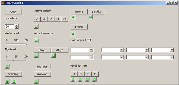
The ImproSculpt4 main GUI window
Quitting
When the main GUI window of ImproSculpt is closed, ImproSculpt (both the gui and audio applications) will quit.
Master settings
The master tempo can be set via the GUI control “tempo bpm”, the unit is beats per minute.
The master clock needs to be turned on for any timed (sequenced, automated) operations in ImproSculpt to run. The master clock can be started or stopped (paused) by using the gui button “Clock” in the upper left of the ImproSculpt main window.
Master audio output level can be set with the “Master Level” slider, and the level for algorithmically generated audio (almost everything except instruments played directly via midi notes) can be set with the “Algo Level” slider.
Utility controls
A set of gui controls that I could not find any other logical place to put yet. This window can be opened by using the “+” button directly above the “Sampling” button.
Probably the most interesting gui control here is the “write to disk” button. This will turn on the writing of ImproSculpt’s master out channels 1 and 2 to a file named “demofile.wav”. Disk write continues until it is turned off by toggling the button off.
Other GUI controls in this window includes a textbox to enter Csound score events (“Csound event”), a button that will initiate printing of all active Csound chn bus channels to the console, and simple and un-intuitive mixer controls for separate internal audio channels. None of this is considered to be of any specific use to an end user.
Sampling
Live sampling is activated by using the “Sampling” toggle button in the main window.
Audio input is written to one long memory slot (Csound ftable), and ImproSculpt keeps a record of in/out points (markers) for separate segments of the live sampled waveform. Segments are automatically created based on audio analysis.
WaveData window
The window can be brought to front by using the “~” GUI button below the “Sampling” button in the main window.
Amplitude, pitch and centroid wave curves, as well as segment markers, for the sampled audio is shown in the “WaveData” window. The wave data for pitch will also give an indication of the pitched/unpitched quality of the audio input. If the input is noisy, the pitch curve will go to its maximum value. Also, if the signal level is more than 1dB below the minimum amplitude (set with the “min thresh” amplitude control), the pitch curve will drop to zero.
Drag and drop segment assignments:
The segments as marked in the WaveData window can be assigned to composition modules by standard drag and drop procedures. Using a mouse, you can grab a segment in the wave display and drop it onto a drop target. Currently, the randPlayer and partikkel modules allow drag and drop assignment of live sampled segments.
The wave display will show a marker corresponding to the module assignments by drawing a thick horizontal line in the segment’s area of the wave display. The line has a different color and a different vertical offset corresponding to the different modules segments can be assigned to.
Live sampling controls
Detailed parameter settings can be found in a separate window, opened by using the “+” gui button below the “Sampling” button in the main window. The following relates to controls in this subwindow.
Input select:
Selection of audio input for live sampling is done with the “input select” gui control
amp response:
The response time when analyzing input amplitude for changes in slope (e.g. a quickly rising slope signifies an audible attack in the audio signal.). The response time sets the time in milliseconds between amplitude slope measurements. Typical values in the range 10 to 30.
attack thresh:
The “amplitude slope steepness” required in the audio signal to qualify as an attack. The value is in dB. If the current amplitude measurement is this many dB’s louder than the previous measurement, then we have an attack point. Typical values in the range 1 to 3.
min thresh:
The minimum amplitude (in dB) needed to consider attack detection at all. This value also sets the minimum amplitude needed for pitch detection (1dB below the value set in the gui control). Typical values in the range -25 to -45.
release thresh:
Controls how much softer the signal must become to qualify as “segment end, or phrase end”. The value is in dB. Typical values in the range -1 to -6.
release time:
The time after the amplitude has dropped below the release threshold still considered part of this segment. This means that if the amplitude briefly drops below the release threshold, we will not consider starting a new segment but continue using the same segment.
pitchThresh:
The allowed pitch variation while still considering the audio as pitched. If pitch variation exceeds the pitchThresh value, consider the audio as noisy (unpitched). The pitch curve display will go to maximum to show that the signal is unpitched.
The value is in relative frequency, e.g. a value of 0.1 will allow the frequency to change +/- 40 Hz if the previous measurement was 400 Hz. Typical values 0.05 to 0.2.
pitchHigh:
Estimated minimum frequency for the pitch detector in Hz. Typical values 50 to 150.
pitchLow:
Estimated maximum frequency for the pitch detector in Hz. Typical values 800 to 1500.
Segment Organizer
A module for automatic sorting of segments is provided in the module “liveSampledSegmentsOrganizer.py”. The module analyzes live sampled segments and maintains lists of segments fulfilling specific sorting criteria, e.g. “shortest segments”. Composition modules (currently only the randPlayer module) may subscribe to auto segment assignment by way of the segment organizer, e.g. a composition module subscribes to the list of shortest segments and gets its segment list updated when new short segments are live sampled. This module currently has no gui controls but it can be scripted. The methods of the module have not yet been standardized, and a layout of the module controls has not been decided on. Most probably, it will be controlled by gui widgets in each separate composition module that subscribes to the segment organizer information.
intervalMelody
This module generates melodies based on a pitch series or interval series. It can generate up to 5 voice polyphony. Each of the 5 voices can be started or stopped by using the “v1” to “v5” toggle buttons in the main window.
Note: The intervalMelody module will not generate any events unless the master clock is running (use the “Clock” toggle button in the main window to start the clock).
The “runChorale” checkbox in the detailed parameter window for intervalMelody must also be enabled for any events to be generated. This enables different ways of starting and stopping several voices together.
Detailed parameter settings can be found in a separate window, opened by using the “+” gui button. The following relates to controls in this subwindow.
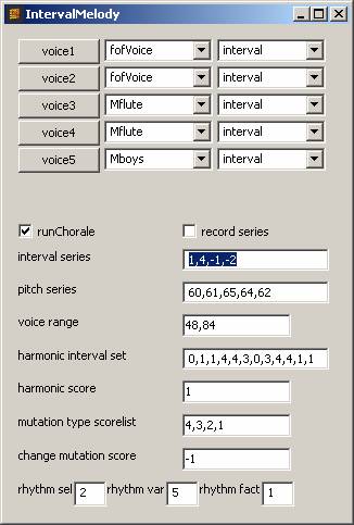
The intervalMelody subwindow
Voice buttons:
The buttons labeled “voice1” to “voice5” are coupled with the “v1” to “v5” buttons in the main panel. They activate melody generation for each voice respectively.
Instrument selection:
To the immediate right of each “voice” button, there is a drop-down menu control for selection of instrument timbre for each voice.
Interval/pitch mode:
To the immediate right of the instrument selection menu controls, there is a drop-down menu control for selecting interval or pitch mode for each voice. Melodies generated in pitch mode will use only the absolute pitches in the pitch series, while interval mode will generate melodies based on the relative intervals between the notes in the series.
runChorale:
This checkbox must be enabled for any events to be generated by the intervalMelody module. This allows stopping (and restarting) all intervalMelody voices together, while the master clock might still run.
record series:
This checkbox enables midi recording of pitch and interval series. When enabled, midi notes input (on any midi channel except channel 5) will be appended to the series. When enabling the checkbox, the currently stored series will not immediately be deleted. When recording is enabled and the first midi note is received, the pitch series will be replaced by that note. After two notes have been received, the interval series will be replaced by the interval between the two notes.
The rules and scores
The intervalMelody module is not a based on a strict serial composition technique, but it considers the series as the primary source material for generating melodies. The series may be permutated (reversed or inversed or both) at any time (does not have to use all items in the series before changing permutation). Intervals or pitches not in the series are also considered valid suggestions for generating the next pitch, provided the rules and scores (e.g. for harmonic relations between simultaneous voices) creates a preference not fulfilled by the series.
intervalSeries:
The series of melodic intervals as a comma separated list of integers. The integers represent the interval in semitones and may be negative. The series may be updated by entering values in the gui control. It is also updated when recording a series via midi note input.
pitchSeries:
The series of absolute pitches as a comma separated list of integers. The integers represent midi note numbers for the pitches. The series may be updated by entering values in the gui control. It is also updated when recording a series via midi note input.
voiceRange:
The voice range as a comma separated list of two integers. The integers represent midi note numbers, the first integer setting the lowest pitch and the second setting the highest pitch in the voice range. The voice range is currently only used for generation of melodies in interval mode. If an interval would make the melody go outside the voice range, the interval is inverted (also inverting the current series permutation).
harmonic interval set:
A set of score values for preferred harmonic relations between simultaneously playing voices. The list of comma separated integers represents the preference score for each of the 12 intervals (prime, minor second, major second, minor third, etc. up to major seventh). For example, a harmonic interval set of 0,0,0,1,1,0,0,2,0,0,0,0 will give preference to melodic pitches creating a harmonic relation of a fifth or (slightly less) third in relation to other simultaneously playing pitches in other voices. Positive values sets preference for using the harmonic interval, negative values are allowed. The effect of the values is relative, as the score for each harmonic interval is compared to the score of all other harmonic intervals.
harmonic score:
A scaling factor for the harmonic interval set, increasing or decreasing the significance of the set. If the harmonic interval set contains negative values, increasing the harmonic score will affect the relative preference value of positive and negative scores in the set. If the harmonic score is set to a negative value, the preference values in the harmonic interval set are inverted.
mutation type scorelist:
A list of 4 integers representing preference values for using each of the four series permutations (normal, reverse, inverted, reverse inverted). For example, a mutation type scorelist of 0,2,0,0 will create a clear preference for using the reverse permutation of the series.
change mutation score:
A single integer representing the preference for changing the permutation of the series. As the rules governing harmonic relations may create a preference for changing the permutation type (e.g. start reversing the pitches), a negative “change mutation” score can act as a countermeasure, forcing the algorithm not to change permutation type.
Rhythm generation
The rhythm of the generated melodies is based on a set of precomposed rhythm patterns. Selection of rhythm patterns are governed by the gui controls “rhythm sel”, “rhythm var”, and “rhythm fact”. When a rhythm pattern is selected by the algorithm, it will use all rhythm events in that pattern before selecting a new one.
rhythm sel:
Selects one of the rhythm patterns, or set the offset for random selection of rhythm patterns.
rhythm var:
The amount of randomness to the rhythm pattern selection. For example, if rhythm sel is set to 4 and rhythm var is set to 3, the algorithm will select randomly between rhythm patterns 4, 5 and 6.
rhythm fact:
The time factor of the rhythm patterns. Typically, one would use integers 1, 2, 4 or 8 to double the tempo for the rhythms. Floating point values are allowed.
The rhythm patterns used
The following applies to advanced users, basic users may skip this paragraph.
ImproSculpt comes with 14 different rhythm patterns, sorted according to rhythmic intensity. The patterns themselves may be modified by editing the self.rhythms variable in the intervalMelody.py python source code file. The format for each rhythmic event is a list of [delta time, duration, velocity]. Delta time specifies the time until the next event, duration specifies the duration of the event, and velocity specifies the dynamics of the event. Each event is enclosed in square brackets, and each rhythm pattern is also enclosed in square brackets, finally the full list of rhythm patterns is enclosed in square brackets. It is suggested to keep a copy of the original rhythm patterns that came with ImproSculpt as there is no error checking for the validity of manually edited rhythm patterns.
randPlayer
The randPlayer triggers the playback of audio segments in rhythmical patterns. It uses a set of precomposed rhythm patterns and selects randomly from the set of assigned audio segments. A polyphony limiter is used to limit the allowed number of simultaneously playing segments. This can create variation in the rhythm patterns, as rhythm events occurring while polyphony is exceeded will not trigger any events.
ImproSculpt uses two instances of this module, each operating individually, with separate segment assignments and parameter controls. Each of the two instances can be enabled by using the “rPlay1” and “rPlay2” toggle buttons in the main window respectively. These buttons also serve as drop targets for dragging and dropping audio segments from the WaveData window.
Detailed parameter settings can be found in a separate window, opened by using the “+” gui button. The following relates to controls in this subwindow.
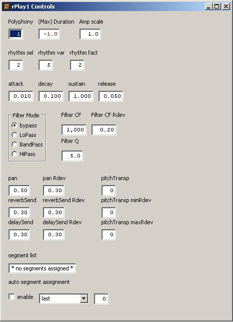
The randPlayer subwindow
Rhythm generation
The rhythm of the generated melodies is based on a set of precomposed rhythm patterns. Selection of rhythm patterns are governed by the gui controls “rhythm sel”, “rhythm var”, and “rhythm fact”. When a rhythm pattern is selected by the algorithm, it will use all rhythm events in that pattern before selecting a new one.
rhythm sel:
Selects one of the rhythm patterns, or set the offset for random selection of rhythm patterns.
rhythm var:
The amount of randomness to the rhythm pattern selection. For example, if rhythm sel is set to 4 and rhythm var is set to 3, the algorithm will select randomly between rhythm patterns 4, 5 and 6.
rhythm fact:
The time factor of the rhythm patterns. Typically, one would use integers 1, 2, 4 or 8 to double the tempo for the rhythms. Floating point values are allowed.
The rhythm patterns used
The following applies to advanced users, basic users may skip this paragraph.
ImproSculpt comes with 14 different rhythm patterns, sorted according to rhythmic intensity. The patterns themselves may be modified by editing the self.rhythms variable in the intervalMelody.py python source code file. The format for each rhythmic event is a list of [delta time, duration, velocity]. Delta time specifies the time until the next event, duration specifies the duration of the event, and velocity specifies the dynamics of the event. Each event is enclosed in square brackets, and each rhythm pattern is also enclosed in square brackets, finally the full list of rhythm patterns is enclosed in square brackets. It is suggested to keep a copy of the original rhythm patterns that came with ImproSculpt as there is no error checking for the validity of manually edited rhythm patterns.
Other module controls
Polyphony:
This control sets the allowed number of simultaneously playing audio segments.
Max duration:
This control sets the maximum duration of each audio event generated by the randPlayer module. If the assigned audio segment is longer than the max duration, the segment will be truncated. If the segment is shorter, it will be played to end. If the max duration is set to -1, no max duration control is applied and the segment length determines the duration of each audio event generated.
Amp scale:
As amplitude of live sampled segments may vary considerably, this control can be used to apply additional amplitude scaling for the randPlayer audio output.
Enveloping:
Controls for amplitude enveloping of each audio event is provided, generating a standard ADSR envelope. The controls are: attack time, decay time, sustain level, and release time.
Filter Mode, Filter CF and Filter Q:
Controls for the adjustment of the characteristics of a filter applied as an insert effect to the audio generated by this module. The filter can be bypassed by setting the filter mode to “bypass”. Filter CF sets the cutoff frequency of the filter, and Filter Q sets the resonance of the filter. The FilterCF Rdev control sets the amount of random deviation from the cutoff frequency, calculated at event rate. Random deviation for cutoff frequency is set as a “offset factor”, so the value is relative to the cutoff frequency, e.g. an Rdev of 0.1 and a CF of 1000Hz will give a max deviation of 100Hz (resulting in a range of 900Hz to 1100Hz).
Pan, panRdev:
Stereo pan position for audio events with 0.0 being hard left and 1.0 being hard right. The panRdev control sets the amount of random deviation from the pan value. Random deviation is calculated at event rate and is a plain offset value, e.g. a pan of 0.5 and a panRdev of 0.2 will pan audio events to the 0.3 to 0.7 range.
reverbSend, reverbSendRdev
Reverb send amount for audio events. The reverbSendRdev control sets the amount of random deviation from the reverbSend value. Random deviation is calculated at event rate and is a plain offset value, see also pan.
delaySend, delaySendRdev
Delay send amount for audio events. The delaySendRdev control sets the amount of random deviation from the delaySend value. Random deviation is calculated at event rate and is a plain offset value, see also pan.
pitchTransp, pitchTransp minRdev, pitchTransp maxRdev:
Pitch transpose in semitones for the playback of sound files or audio segments. The “minRdev” and “maxRdev” controls set the minimum and maximum amount of random deviation in semitones.
segment list:
The list of audio segments currently assigned to the module, as a list of comma separated integers. This control is updated when segment assignments are done (e.g. by dragging and dropping segments from the WaveDisplay, or by automatic assignment updates due to segment analysis in the segment organizer).
Direct control over segment assignments can be done by entering segment numbers in the gui control.
Auto segment assignments:
These controls relate to the segment organizer for automatic assignment of live sampled segments to the composition module.
enable:
Enable automatic segment assignments.
Feature list:
A drop-down menu of features (last/first/shortest/longest) used to assign live sampled segments. For example, if one chooses “shortest”, the n shortest live sampled segments will be assigned to the module.
Number of segments:
The number of segments to assign.
Direct midi note triggering of randPlayer1:
If the “mNote” checkbox in the main window is enabled, the randPlay1 module may be triggered via midi notes. In this mode, the live sampled segments are selected according to midi channel. Notes on midi channel 1 triggers playback of the first segment in the module’s segment list, notes on channel 2 triggers the second segment, and so on. If there are fewer segments in the segment list than the midi channel number used, the segment will be selected randomly from the segment list. Midi channel 5 is used for special control purposes, and will not trigger any randPlayer segments. When triggering segments via midi, the segment is transposed according to the midi note number used to play the note. Note number 60 will play back the segment at the original recorded pitch, while other note numbers will give transposition in semitones relative to note number 60.
vectorHarmonizer
The vector harmonizer is used to harmonize a melody note. Based on an interval vector, it generates a number of alternatives for the chord to be used for harmonizing. A set of weighted rules are used to select among these chord suggestions.
The duration of the chord will be equal to the duration of the melody (midi input) note and the melody note is considered part of the interval vector chord.
Detailed parameter settings can be found in a separate window, opened by using the “+” gui button. The following relates to controls in this subwindow.
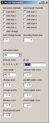
The interval vector harmonizer subwindow
About interval vectors
An interval vector represents a collection of pitch sets with the same internal intervallic relations. Technically speaking, an interval vector is the sum of all intervals between all pairs of pitches in a pitch class set. Intervals larger than a tritone are inverted, e.g. a major sixth equals a minor third. For more information about interval vectors, see [1] and [2].
Enabling the harmonizer
The GUI has check boxes to enable harmonizing for separate midi channels, labeled “harmonize channels”. By checking one or more of these boxes, harmonizing is enabled for the respective midi channel.
Directly below these check boxes are also GUI controls for “auto vRange” and “auto vRange border”. These are used to set the suggested voice range for the harmonizer. If the “auto vRange” box is checked, the last midi input note is used as the center of the suggested voice range and the “auto vRange border” sets the width of the voice range. If the midi note has a note number of 60, and the “auto vRange border” has a value of 7, the voice range is set to (53, 67). More information on voice range is given under rules and scores.
Recording of interval vectors
Interval vectors may be generated on the fly from midi input. This is enabled by using the check boxes labeled “record pcset channels”, recording is enabled on a per channel basis similar to the “harmonize channels” check boxes. When recording interval vectors by means of midi input, note numbers that are received simultaneously are grouped and analyzed. The term “simultaneously” is loosely used here, meaning “events that are received within the same time window”. The size of the time window is set by using the “recording thresh time” GUI control, and the unit of measurement is milliseconds. For example, if the recording thresh time is set to 50 milliseconds, notes that are received less than 50 ms apart are grouped.
The group of notes is then reduced to a pitch class set, and this pitch class set is used to look up the corresponding interval vector in a dictionary.
Pitch class sets may also be input via the GUI, using the “pc set” GUI control. This control will accept integers in the range 0 to 11, spaced by a comma (e.g. “0, 1, and 5”). The GUI widget “interval vector” will display the currently used interval vector. It is not possible to enter an interval vector directly as it is quite possible to invent non-existent vectors, and it is more intuitive to enter a pitch class set.
Selecting an instrument for the chord notes
The instrument timbre for playback of the chords may be selected using the drop-down menu “instrument select”. A special instrument labeled ‘MidiOut’ will send notes to an external synthesizer on midi channel 1 (if midi out is enabled).
The rules and scores
A number of rules are used to give each alternative chord a score value. The chord that best fits the selection criteria as set by the rules. The rules may be weighted by adjusting the score factor for each rule. The score factor is relative, so that setting all rules to a score of 100 will give the same result as setting all scores to 1. The score factor for each rule may also be set to a negative value, and the rule will then try to accomplish the opposite of its labeled effect.
Voice range:
A suggested voice range may be set with the “voice range” GUI control. Chords that contain notes outside this range will be given a penalty score (less likely to be selected). The penalty for out of range notes are adjusted with the “vRange score” GUI control.
If the previous chord contained out of range notes, and the next chord will try to move even further out of the suggested voice range, and extra penalty is given. This is thought of as creating a “gravity” field, trying to move out of range voices back into range. The strength of this field may be adjusted with the vRange gravity” GUI control.
Distance from previous chord:
When moving from chord to chord, one may calculate the distance in semitones each voice needs to travel to reach the new chord. For smooth transition from chord to chord, this distance should be as small as possible. The “distance score” GUI control adjusts the relative weight of this feature, higher values means the feature is more important.
Common notes:
When moving from chord to chord, one may count the number of notes the old chord has in common with the next chord. As with the distance parameter, this also affects the smoothness of the transition from chord to chord. The “common note score” GUI control adjusts the relative weight of this feature, higher values means the feature is more important.
Parallel motion:
This rule checks for parallel motion in voices when moving from chord to chord. Higher values in the “parallel motion score” GUI control will give preference to chord voicings that does not result in parallel motion. Contrary motion in any voices will act as a counterweight for this rule, so in effect what is adjusted is the balance between parallel and contrary motion.
Chord spread:
The voicing of a chord may be tightly spaced (all notes of the chord spaced close together in a cluster) or spread out over a wider pitch range. Using higher values in the “chord spread score” GUI control give more preference for chords that have a greater spread.
Chord history (repeat and toggle):
A memory of the previous chord and the second previous chord is kept in the module. This can be used to avoid repeating the same chord over and over endlessly (would fit the voice leading rules just fine), or toggling back and forth between two chord. Higher values in the “chord repeat score” GUI control will make the algorithm try to avoid repeating the same chord, and higher values in the “chord toggle score” GUI control will make the algorithm try to avoid toggling back and forth between two chords.
tws
A legacy of the Flyndre audio installation, this is just a Risset glissando of filtered noise with some sparkling “beads”. No detailed parameter control is provided in the GUI. One could use this module to test that ImproSculpt is running and audio out working.
feedbackInstr
This instrument utilizes audio feedback to create continuously changing timbres. A slow feedback eliminator was enables a feedback signal to establish (using microphone input and audio out) while dynamically controlling the harmonics in the feedback signal. The feedback will typically consist of resonant frequencies in the feedback loop, these frequencies are tracked by the feedback eliminator and gradually attenuated. When the strongest frequencies have been attenuated, other resonant frequencies will introduce themselves in the feedback loop. In this was, the feedback instrument explores and utilizes the resonant frequencies in the feedback loop one by one. External resonators can be used to modify the feedback loop, and in that case, a physical manipulation of the resonators affects the resulting prominent frequencies in the audio output. The feedback instrument has an additional internal resonator circuit, an internal feedback circuit as well as delay lines and filtering to enable an additional level of control of the timbre generated.
Detailed parameter settings can be found in a separate window, opened by using the “+” gui button. The following relates to controls in this subwindow.
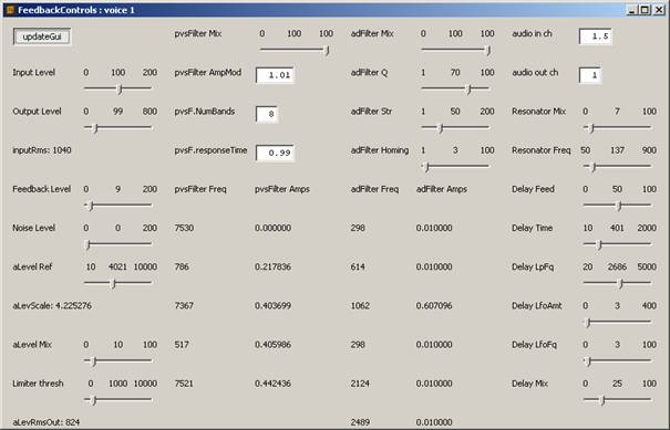
The feedback instrument subwindow
updateGui:
This button will enable automatic GUI updates in the module. This will display the changing input levels, the most prominent frequencies in the signal, and in what way the amplitude of these frequencies are attenuated. As the system load of updating a lot of GUI widgets frequently can be high, this is disabled by default. Normally, one would enable GUI updates when investigating for suitable parameter settings, and then possibly disable GUI updates while performing with the instrument.
Input Level:
This control scales the audio input level to the module.
Output Level:
This control scales the audio output level from the module.
inputRms:
Display of the RMS amplitude of the input signal.
Feedback Level:
This control sets the amount of internal feedback. It can be used to induce feedback in the absence of an external feedback loop, or to add a different set of harmonics to the external feedback loop.
Noise Level:
This control sets the amplitude of a noise generator. Can be used to add bursts of noise into the feedback loop.
aLevelRef:
Sets the reference level for the auto level processing stage. The auto level processing stage can be considered a type of extremely hard compressor/limiter that attempts to keep a constant signal level.
aLevScale:
Display the amplitude scaling factor effectuated by the auto level processor.
aLevel Mix:
The dry/wet mix for the auto level processor.
Limiter thresh:
This control sets the amplitude threshold for compression/limiting of the instrument’s master output.
pvsFilter Mix:
The dry/wet mix for the pvs filter. This filter is a FFT-based feedback eliminator filter, build upon the pvs opcodes in Csound. The filter analyzes the audio signal to determine the frequency bands with the highest energy levels and proportionally attenuates the amplitude of those frequency bands.
pvsFilter AmpMod:
This control sets the (master) amount of amplitude modification for the pvs filter.
pvsF.NumBands:
This control sets the number of frequency bands that the pvs filter should process. For example, if the value of the control is set to 8, the energy of the 8 strongest frequency bands is attenuated while the rest of the signal is left untouched.
pvsF.ResonseTime:
This control sets the response time of the pvs filter. If the control is set to 1.0, the filter will calculate new attenuation factors once per 1.0 seconds.
pvsFilter Freq:
Displays the frequencies of the strongest frequency bands for which the filter is active.
pvsFilter Amps:
Displays the amplitude attenuation factor of the strongest frequency bands for which the filter is active.
adFilter Mix:
The dry/wet mix for the adaptive filter. This filter is another form of feedback eliminator filter based on pitch tracking. The audio signal is analyzed for the most prominent pitch(es), and a parametric equalizer is applied to attenuate these frequencies. The signal is divided into four overlapping frequency bands, each with its own parallel pitch analysis and equalizer stage. In addition, two analysis and equalizer stages are configured in series (post processing the output from the parallel filters. The filter operates in such a manner that when the analyzed pitch changes, the frequency for the parametric equalizer will glide to the new pitch. In this respect, the filter may well attenuate non-feeding parts of the signal while gliding. This method of feedback reduction is not theoretically correct, but in the context of this specific instrument it was found that it can be used to good effect in combination with the pvs filter.
adFilterQ:
The Q factor for the parametric equalization.
adFilter Str:
The strength of the adaptive filter, e.g. how much attenuation is effectuated by the parametric equalizer. The control sets a “master” strength, and each separate filter calculates a relative attenuation factor according to the strength of each analyzed pitch.
adFilter Homing:
The homing frequency (/10) of the different equalizer bands. This determines how fast the equalizer bands will adjust to changes in the pitch analysis. A value of 100 will allow the equalizer bands to change at a rate of 10 Hz.
adFilter Freq
Displays the frequencies for which the filter is active.
adFilter Amps
Displays the amplitude attenuation factor of the frequencies for which the filter is active.
Audio in ch:
This control selects the audio input to use for the module. An index based mixing is used, so that input numbers may be fractional. For example, using an input ch of 1.5 will let the module receive audio from inputs 1 and 2 with equal amplitude from each.
Audio out ch:
This control selects the audio output to use for the module.
Resonator Mix:
The dry/wet mix for an internal resonator effect. The resonator may be used to add specific frequencies into the feedback loop.
Resonator Freq:
The fundamental frequency of the internal resonator. In addition to the fundamental frequency, harmonic resonators at 2, 3, 4 and 5 times the fundamental frequency are added (with lower feedback values for the higher harmonics).
Delay Feed:
This control sets the amount of (delay line) feedback for the delay insert effect.
Delay Time:
This control sets the delay time for the delay effect.
Delay LpFq:
This control sets the cutoff frequency of a lowpass filter, situated in the delay line feedback loop. To some extent, varying the cutoff frequency here affects the amount of high frequencies in the overall feedback loop.
Delay LfoAmt:
Amount of LFO modulation of the delay time, can be used to create a slow pitch modulation in the overall feedback loop.
Delay LfoFq:
Frequency of the delay line LFO. The value is in Hz/100, so a value of 50 will give a LFO frequency of 0.5 Hz.
Delay Mix:
The dry/wet mix for the delay effect.
drumloop
A legacy of ImproSculpt Classic. This module has not found a natural place in ImproSculpt4, and the current implementation largely copies the functionality of ImproSculpt Classic. However, the layout and specification of the gui control look quite different, and no midi control is currently implemented.
The drumloop module will play back audio files loaded from disk and loop them every 8 beats. There are 3 separate layers of loops, sharing the same loop points.
Amplitude for each layer is set with the controls “amp layer n”, and the master amplitude is set with “amp master”.
The playback speed of the audio loops is set by adjusting the “pitch control.
Selection of audio file for each layer is done with the “loop layer n” controls, and the numbers refer to sound files loaded in the “inc/drumloop_ftables.inc” Csound file.
Separate breakbeat (based on the Csound opcode bbcut) processing is applied to each layer, with a breakbeat cutting mix (dry/wet) set by the “BbMix layer n” controls. Bbcut parameters can be set with the “Bb subdiv”, “Bb barlen”, “Bb Phrbar”, “Bb Numrep”, “Bb StutSpd”, and “Bb StutRnd” controls, these reflect the parameters to the bbcut opcode in Csound. Details for the bbcut opcode can be found in the Csound manual.
Each layer has a separate hipass and lowpass filter. The hipass and lowpass filtering are combined in such a way that two input controls (HP and LP) will enable control of bypass, bandpass, hipass cutoff frequency and lowpass cutoff frequency. If both HP and LP are set to 0.0, the filter is bypassed. As HP is increased, low frequencies are increasingly attenuated and the filter cutoff frequency will rise. As LP is increased, high frequencies are increasingly attenuated and the filter cutoff frequency will drop. Some experimentation is encouraged to get used to the effect of these controls.
The “Fill” buttons will engage a post-processing (post bbcut and filtering) manual beat cutter, cutting/repeating the audio to set subdivisions of the clock.
partikkel (single voice)
The single voice partikkel is a granular processing module for live sampled segments of audio files loaded from disk. It was designed to be controlled from an external hardware controller (e.g. via midi), and the gui controls reflect the control inputs available. It is possible but impractical to control the module via gui without the use of a hardware controller.
The module is activated by using the “partikl 1” or “partikl 2” buttons in the main panel.
Selection of waveforms for granular processing can be done via the gui drop-down menus in the main window. Waveform selection (segment assignment) can also be done by dragging and dropping segments from the WaveDisplay onto these drop-down menu controls. Finally, segment assignment can be done via midi.
The waveform selection for single voice partikkel module 1 and partikkelCloud is linked, and uses the same waveform assignments. 4 waveforms are assigned to a partikkel generator, allowing a crossfade between waveforms inside each grain.
For a full understanding of partikkel’s capabilities, please refer to the Csound manual page for the partikkel opcode. The ImproSculpt single voice partikkel represents a subset of the partikkel opcode’s features.
Amp:
Output amplitude scaling.
GrFreq:
Grain frequency (e.g. grain rate)
Transp:
Transposition, playback rate of the waveform inside each grain.
Dur:
Grain duration, relative to grain rate.
Attack:
Attack time for each grain, relative to grain duration.
FmIndx:
Frequency modulation index for modulation of the waveform inside each grain.
FmFreq:
FM frequency (see also FmIndx), if the frequency is set to a value lower than 1, the waveform itself will be used as the FM waveform, resulting in feedback modulation.
SweepDur:
Pitch sweep duration for transposition modulation inside each grain.
ChMask2:
Channel masking of separate grains. A set sequence of channel masking output routings is implemented and this control sets the “loop end” point for channel mask indices. The channel masking sequence is: 1= hard pan left, 2=hard pan right, 3=pan left and efx send to chorus effect, 4=pan right and efx send to reverb effect.
GainMask2:
Gain masking of separate grains. A set sequence of grain amplitudes is implemented and this control sets the “loop end” point for gain masking.
St.width:
Stereo width for the channel masking outputs. 0 to 100 range. A value of 0will give mono output while a value of 100 will give maximum stereo spread.
DisplDly:
Delay time for grains sent to channel masking output 2. The delay time is relative to the grain rate, and a DisplDly of 100 will delay ch2 grains by 1/grainrate. This can be used to create pulse width modulation type effects.
ReverbAmt:
Scaling of the reverb send amount for ch4 grains.
JoyX, JoyY
These controls are used to mix between the 4 waveforms used a source for grains. JoyX crossfades between waveforms (1, 3) and (2, 4) while JoyY crossfades between waveforms (1, 2) and (3, 4).
A more intuitive setup would be to use a “joystick” gui control, but none could be found in the wxWidgets library so faders were substituted. If using a “joystick” control, max amplitude for each of the 4 waveforms would be situated at each corned of the xy joystick pad and the x, y coordinates used to interpolate between waveform amplitudes.
Time:
Time pointer into source waveforms. The waveform inside each grain is read starting at the time position set by this control, with 0 representing the start of the waveform and 100 representing the end.
partikkelCloud
This module generates 4-voice granular cloud automation, sending the automated parameters values to 4 partikkel instruments in Csound. As each cloud contains some 300 parameters, a selection of metaparameters have been created to modify the automation during realtime performance. The application “Partikkel Cloud Designer” (also by Øyvind Brandtsegg) allows a detailed and precise specification of parameter values, storing the values to preset files. Each preset contains start, middle and end values for each parameter, as well as segment duration and segment curvature for the transition from e.g. start to middle value. One such preset file is thought of as “a cloud”. In ImproSculpt, the cloud preset files are read into memory, and they can be sequenced. Two special presets (“interpolate” and “static”) can be used to create transitions from cloud to cloud as well as static sections.
The module is activated by using the “p.cloud” button in the main panel.
Parameter controls for the module is found in the window “CloudControls”, which can be opened by using the “+” button next to the “p.cloud” button in the main panel.
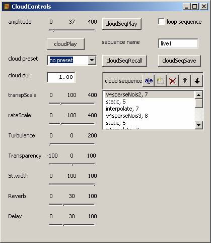
The cloudPlayer subwindow
Amplitude:
This fade sets the master output amplitude of the module.
cloudPlay button:
The button triggers one-shot playback of a cloud preset.
cloudPreset:
Selection of a cloud preset for one-shot playback
cloudDur:
Sets the duration for one-shot playback of cloud presets.
transpScale:
This control dynamically scales (all) the transposition parameters in a cloud preset during playback. Setting the control to 100 will play back the cloud with no transposition scaling.
rateScale:
This control dynamically scales (all) the grain rate parameters in a cloud preset during playback. Setting the control to 100 will play back the cloud with no rate scaling.
Turbulence:
This control dynamically scales all random deviations from partikkel parameters in a cloud preset during playback. Setting the control to 0 allows no random deviation.
Transparency:
This control dynamically affects the grain rate, grain duration, and random masking of grains. In this respect, it is a meta parameter controlling the overall transparency of the resulting sound. Setting the control to 0 will play back the cloud with the original saved settings for these parameters. Increasing the value of the control will give a more transparent sound, decreasing the value will give a more dense sound.
St.width:
This control sets the stereo width for audio output of cloud particles. A cloud preset may have a specification of stereo spread, e.g. using the partikkel opcode’s channel masking feature. Setting the control to 0 will give mono output, regardless of any spatial information embedded in the cloud preset, setting it to 100 will play back the cloud with its original spatial information.
Reverb:
Reverb send amount for single grains. A cloud preset may have reverb send enabled for separate cloud particles, e.g. using the partikkel opcode’s channel masking feature. This control scales the amount of reverb send.
Delay:
Delay send amount for single grains. A cloud preset may have delay send enabled for separate cloud particles, e.g. using the partikkel opcode’s channel masking feature. This control scales the amount of delay send.
cloudSeqPlay button:
The button starts playback of a sequence of cloud presets, as specified in the cloud sequence list control.
Loop sequence:
When this checkbox is enabled, the sequence specified in the cloud sequence list control is looped.
Sequence name:
Set the name of a cloud sequence file to load or save (cloudSeqRecall/Save).
Valid sequences for loading are the cloud sequence files (*.csq) currently residing in the “/presets” directory under ImproSculpt. When typing the file name in the gui control, the file extension should be omitted (e.g. typing “test” will write to the file “test.csq”)
cloudSeqRecall:
Read a cloud sequence from file and load it into the cloud sequence list control. File name is specified with the “sequence name” control.
cloudSeqSave:
Save the sequence specified in the cloud sequence list control to file, using the name provided in the “sequence name” control. No “file overwrite checking” is provided, do take care to use unique file names when saving unless you intend to overwrite an existing sequence file.
Cloud sequence list:
This is a list of cloud presets for sequenced playback. The list has the following format: cloudName, duration. The cloudName points to a partikkel cloud, and duration sets the duration for this cloud preset during sequenced playback. There are two special cloud presets: “static” and “interpolate”. A static preset sets the automation on hold for the duration specified, and an interpolation preset interpolates from the current parameter settings (whatever state the partikkel cloud playback generator is in now) to the next specified partikkel cloud in the list. It should be noted that using an “interpolate” preset at the end of a cloud sequence does not make any sense, as there is not any next cloud preset to interpolate to.
Manual editing of the sequence in the cloud sequence list is possible by using the list controls at the top of the list (edit item, new item, delete item, move item up, move item down). The user is responsible for specifying valid cloud preset names when editing. Valid presets are the cloud preset files (*.clo) currently residing in the “/presets” directory under ImproSculpt. The file extension should be omitted when typing in the cloud sequence list (e.g. typing “test” refers to the cloud preset “test.clo”).
Midi controlled synthesizer
ImproSculpt’s midi controlled synthesizer will respond to midi notes on channels 1,2,3,4 and 6. It will also respond to midi program change messages on any channel (selecting instrument timbre for channels 1,2,3,4 and 6). An overview of program change numbers and instrument timbres can be found in the midi implementation chart.
Midi implementation chart
See the file “ImproSculpt4 Midi Implementation Chart.pdf” for an overview of the midi input mapping for control of ImproSculpt.
The console
(for advanced users)
As an addition to controlling ImproSculpt via the Graphical User Interface and via midi, it is also possible to use a command line type of interface. This can be useful when debugging new modules, or for ad hoc scripting purposes. The console interface runs in a separate application (to run it, type “console_pyro.py” in a terminal window). All methods in the eventCaller can be called from the console. For example, type: “eventCaller.liveSamplingActivate(1,1)” and hit enter. Live sampling will now be active and the sampling status will show in the Gui (sampling button is depressed and the waveplot window starts drawing the waveform data for input audio).
For a full overview of available commands, refer to the source code in the file /control/eventCaller.py
Presets
Preset settings for ImproSculpt may be recalled. Currently there is not preset store methods, but presets may be crafted manually by writing simple python calls. The presets can be found in the python source code file /control/presets.py. As with the console commands, any method in the eventCaller may be called when recalling a preset. By looking at the code in presets.py and in eventCaller.py it should be possible for a python literate user to write his or her own presets.
Preset recall can be done via midi, by sending notes on midi channel 16, the note number determines the preset number (starting at note number 61). Trying to recall nonexistent preset will do not harm. Note that a preset does not have to include settings for all ImproSculpt parameters, only the parameters included in the preset will be updated while all other parameters are left untouched.